Arduino - 读取模拟电压
此示例将向你展示如何读取模拟引脚 0 上的模拟输入。analogRead() 从输入读取模拟电压,并打印到 Arduino 软件(IDE)的串行监视器。
需要的组件
你将需要以下组件 -
- 1×面包板
- 1×Arduino Uno R3
- 1×5K 可变电阻(电位器)
- 2×跳线
程序
按照电路图并连接面包板上的组件,如下图所示。

电位器
电位计(或电位器)是一种简单的机电传感器。它将来自用户的旋转或线性运动转换为电阻变化。
我们所知道的电位器最初被称为变阻器(一种可变线绕电阻器)。各种可用的电位器现在非常惊人,并且初学者可能很难确定哪种类型适合于给定的任务。一些不同的电位器类型,可以全部用于相同的任务,使工作更难。
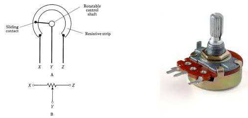
左侧的图像显示了电位器的标准示意符号。右边的图像是电位计。
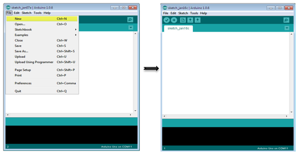
草图
在你的计算机上打开 Arduino IDE 软件。用 Arduino 语言编码将控制你的电路。单击“新建”打开新的草图文件。
Arduino 代码
/*
   ReadAnalogVoltage
   Reads an analog input on pin 0, converts it to voltage,
   and prints the result to the serial monitor.
   Graphical representation is available using serial plotter (Tools > Serial Plotter menu)
   Attach the center pin of a potentiometer to pin A0, and the outside pins to +5V and ground.
*/

// the setup routine runs once when you press reset:

void setup() {
   // initialize serial communication at 9600 bits per second:
   Serial.begin(9600);
}

// the loop routine runs over and over again forever:

void loop() {
   // read the input on analog pin 0:
   int sensorValue = analogRead(A0);
   // Convert the analog reading (which goes from 0 - 1023) to a voltage (0 - 5V):
   float voltage = sensorValue * (5.0 / 1023.0);
   // print out the value you read:
   Serial.println(voltage);
}
代码注意
在下面给出的程序或草图中,你在设置功能中所做的第一件事就是在电路板和计算机之间以每秒 9600 位的速度开始串行通信 -
Serial.begin(9600);
在代码的主循环中,你需要建立一个变量来存储来自电位计的电阻值(介于 0 和 1023 之间,非常适合 int 数据类型) -
int sensorValue = analogRead(A0);
要将值从 0-1023 更改为与电压对应的范围,引脚正在读取,你需要创建另一个变量,浮点数并进行一些计算。要缩放 0.0 到 5.0 之间的数字,将 5.0 除以 1023.0 并乘以 sensorValue -
float voltage= sensorValue * (5.0 / 1023.0);
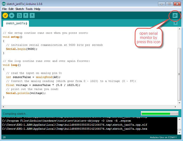
最后,你需要将此信息打印到串行窗口。你可以使用最后一行代码中的 Serial.println() 命令执行此操作 -
Serial.println(voltage)
现在,通过单击顶部绿色栏右侧的图标或按Ctrl + Shift + M打开 Arduino IDE 中的串行监视器。
结果
你将看到稳定的数字流,范围从 0.0 到 5.0。当你转动电位器时,数值会改变,对应于引脚 A0 的电压。